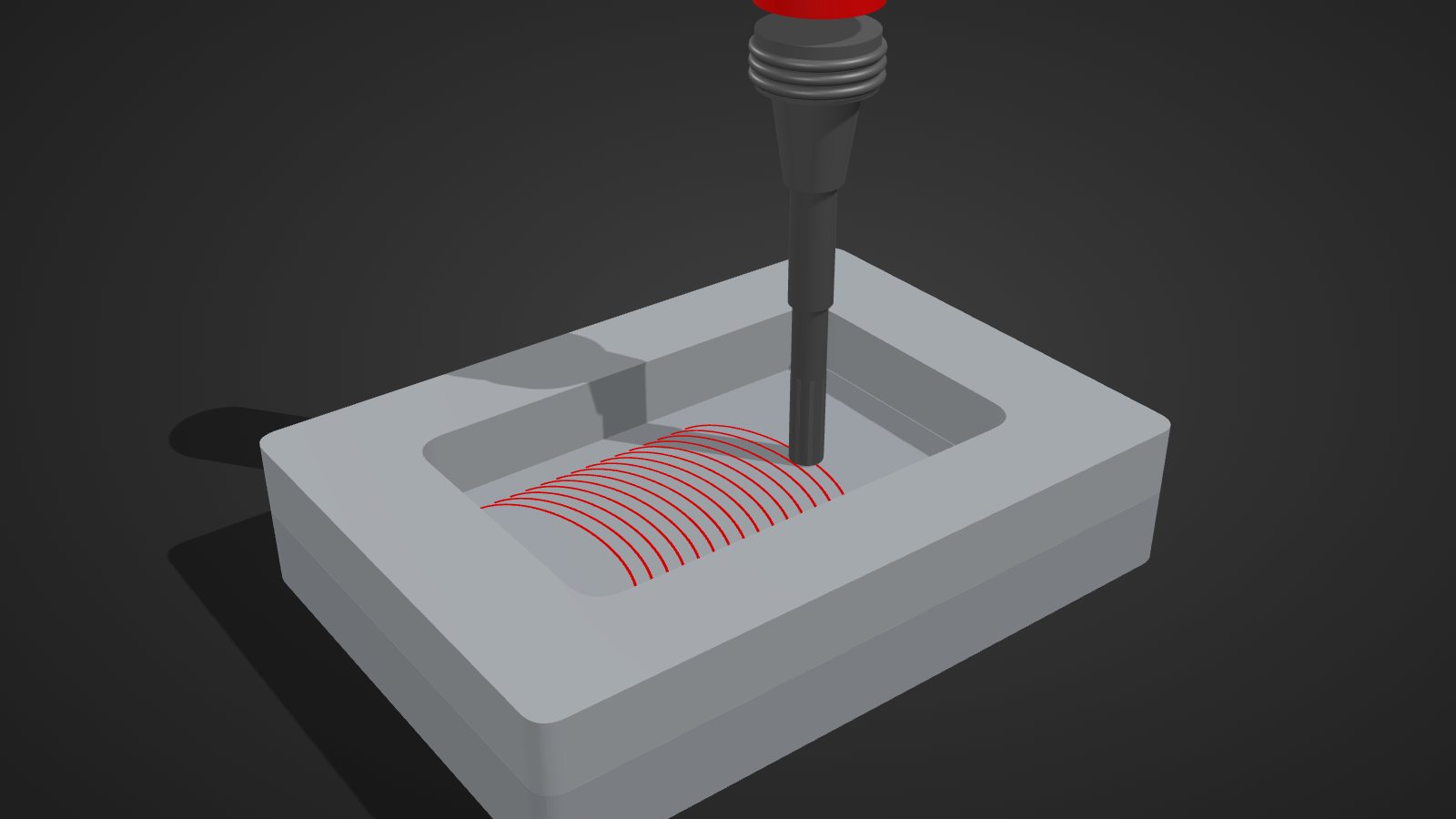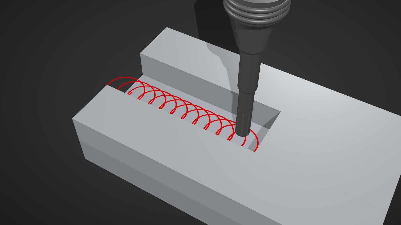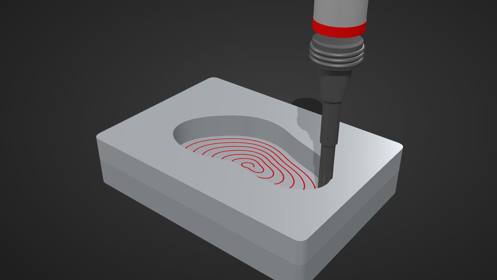
The goal: constant load instead of constant stepover
Conventional contour-parallel toolpaths keep the stepover constant. As a result, engagement fluctuates: in corners and when moving between passes, the cutter suddenly wraps around much more material. iMachining turns this around. The controlling variable is the engagement angle φ, the part of the tool circumference currently in the material. The stepover follows from it and is allowed to vary.
According to the patent, the method pursues several goals at once: minimise the rate of change of the engagement angle over time, adjust the feed to the engagement angle, keep the tool load roughly constant and minimise total cost from machine time and tool wear.
Step 1: dividing the cross-section into regions
At each depth step, the cross-section to be cleared is divided into regions. What matters is whether the edges are open (the tool can approach from outside) or closed (part wall):
| Region | Edges | Toolpath type |
|---|---|---|
| Type I | open edges only | converging spiral from outside in |
| Type II | open and closed edges | trochoidal-like paths |
| Type III | closed edges only (pocket) | diverging spiral from inside out |
The method tries to machine as much area as possible with spirals, because spirals cut without air moves and are therefore the most efficient.
Step 2: the morphing spiral
The core of the patent is the morphing spiral: a spiral that gradually transforms the shape of one contour into the shape of the other, for example from the rectangle of the outer boundary to the circle around an island. Unlike a simple racetrack spiral, it adapts a little more with every loop.
- Bridges: connecting lines are placed between the outer and inner contour. Their length divided by the largest and smallest allowed stepover limits the possible number of loops.
- Number of loops: several candidate loop counts are compared by machining time, and the fastest wins.
- Point by point: each new spiral point lies on the next bridge. Its position is adjusted by binary search until the engagement angle reaches the target value between minimum and maximum.
Step 3: islands, bottlenecks and leftovers
Not every shape can be cleared with a single spiral. The patent describes further building blocks for this:
- Moat around islands: a channel cut with trochoidal-like moves separates the island from the remaining material. According to the patent, its width is preferably at least 2.5 times the tool radius.
- Separating channel at bottlenecks: a channel through a narrow area splits the region into two independent regions, each then machined with its own spiral.
- Leftovers: areas the spiral cannot reach are machined with trochoidal-like paths, i.e. cutting arcs with a return path.
- Recursive: the whole process repeats for every sub-region and every depth.
The Technology Wizard: cutting data for every toolpath point
The toolpath alone is not enough. According to SolidCAM, the Technology Wizard calculates synchronised values for feed, spindle speed, axial depth, engagement angle and chip thickness for every point on the toolpath. It is based on material, tool, workholding and machine limits. A slider with eight levels adapts the values to less rigid setups.
Patent and context
European patent EP 2 681 683 B1 "Computerized tool path generation" by SolidCAM Ltd. has a priority date of 28 February 2011 and was granted in 2020. Google Patents lists 2032 as the anticipated expiry. That is a database estimate, not a legal assessment. Building blocks such as trochoids or engagement-dependent feed were known before. What is protected is the specific combination and calculation method. iMachining is available in SolidCAM and as a version for Siemens NX.
Frequently asked questions
Is iMachining the same as trochoidal milling?
No. The main toolpath is the morphing spiral. Trochoidal-like paths are only used where the spiral cannot reach, and for moats and separating channels.
Why is the stepover not constant in iMachining?
Because the engagement angle is the controlling variable. To keep it within the band, the stepover has to adapt to the geometry, differently in corners than along straight sides.
May I program such a strategy myself?
The patent protects the combination described. Anyone developing their own software with similar toolpaths should have a freedom-to-operate review done by a patent attorney before use. This article is not legal advice.