What a 3D scan delivers
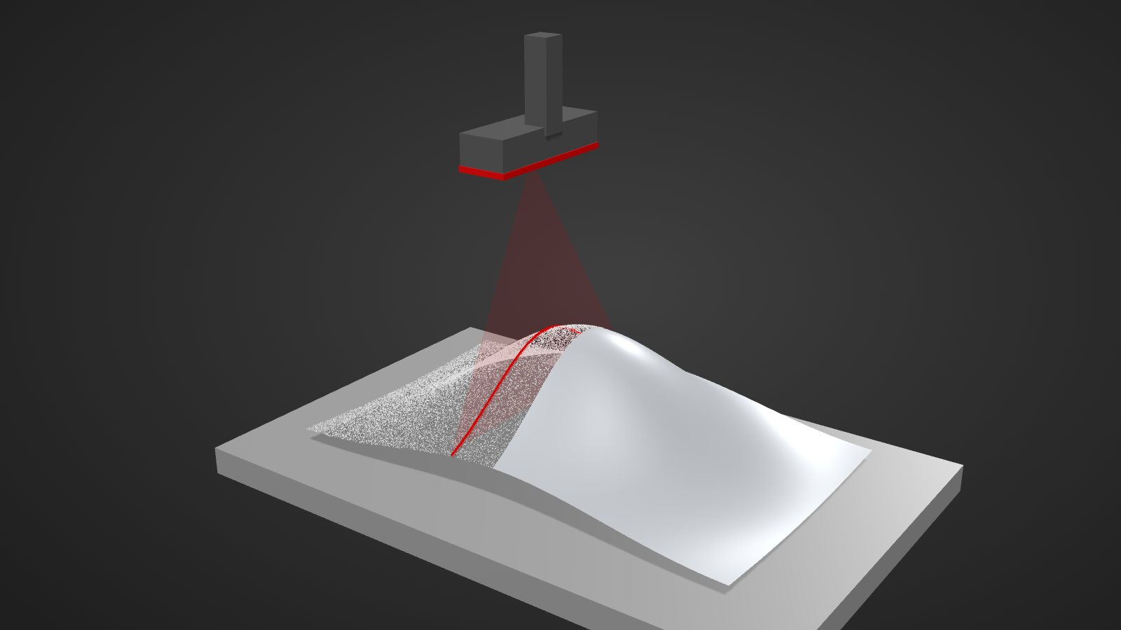
Optical scanners, laser scanners or tactile measuring systems capture the surface of a part as a point cloud. From this, a triangle mesh is usually created, for example as an STL file. Such a mesh describes the shape but contains no design information: no exact cylinders, no planes, no dimensions or tolerances.
Three ways from scan to NC program
- Milling directly on the mesh: many CAM systems can calculate toolpaths directly on a mesh. Good for freeform surfaces, models and copies, provided the scan quality is right.
- Reverse engineering: a clean CAD model with surfaces and regular geometry is rebuilt from the mesh. More effort, but necessary when dimensions, tolerances and changes matter.
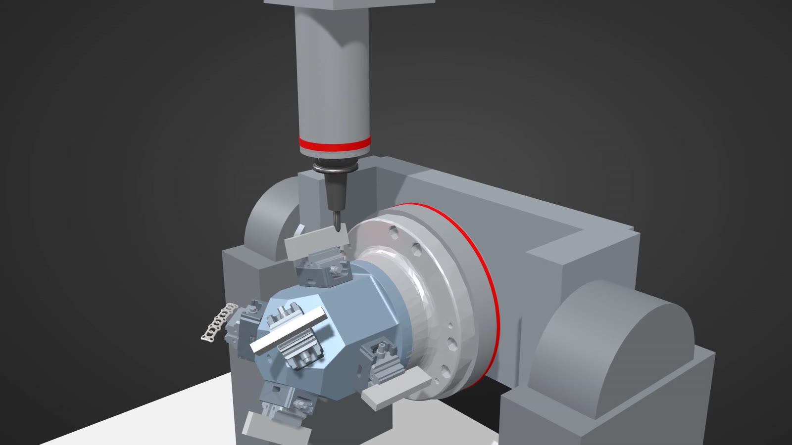
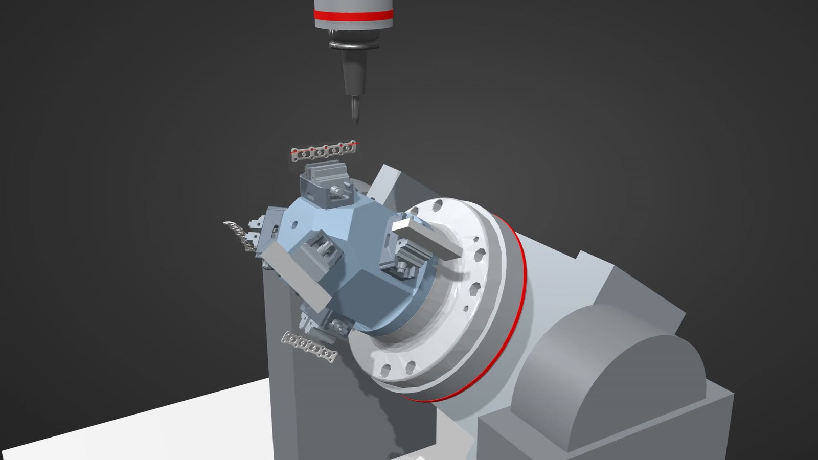
- Scan as stock: the scan of a casting, forging or 3D printed part serves as the stock model. CAM then knows the actual allowance and avoids air cuts or overload.
Alignment: bringing scan and nominal together
For scan and CAD model to match, they are aligned to each other, usually with a best-fit method. For manufacturing, what matters is which surfaces serve as the datum. A wrong alignment moves the allowance to where it is missing.
Typical applications
- Spare parts for which no drawing or CAD model exists any more.
- Repair and rework, for example on molds or worn parts.
- Stock from casting, forging or additive manufacturing with uneven allowance.
- Handmade models or design samples that are to be milled.
Limits and what to watch
- Accuracy: the accuracy of the scan limits the accuracy of the result. Tight tolerances need reverse engineering referenced to the drawing.
- Mesh quality: holes, noise and very dense meshes make toolpath calculation harder. A cleaned, sensibly reduced mesh saves computing time.
- Wear and distortion: a scan shows the actual state, including wear. For spare parts you have to decide which shape is actually intended.
Frequently asked questions
Can you mill an STL file directly?
Yes, many CAM systems calculate toolpaths on meshes. For fits and tight tolerances, a reverse-engineered CAD model is the better basis.
What is reverse engineering?
Creating a CAD model from scan data. Regular geometry such as planes and cylinders is recognised, and freeforms are rebuilt with surfaces.
How accurate is a 3D scan?
That depends heavily on the scanner, the part and the surface. For manufacturing, what counts is whether the accuracy matches the required tolerance.